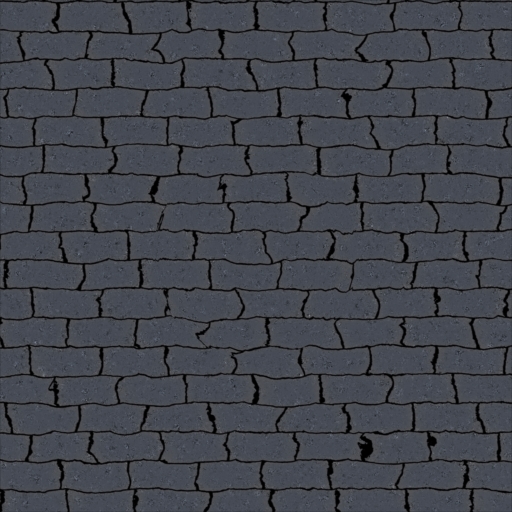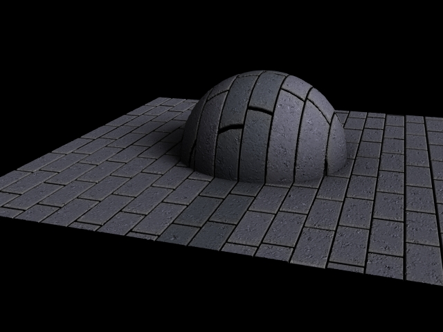

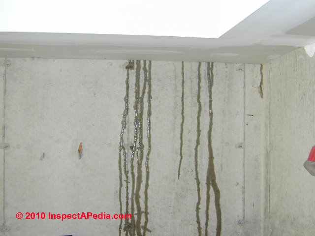
The next fun feature is going to be water stains. They are driven by gravity so they will be primarily based on a user input ramp whose position is from the Y axis. The interesting part will be getting the "seepage" part right, possibly only making that feature available when tiles are selected.
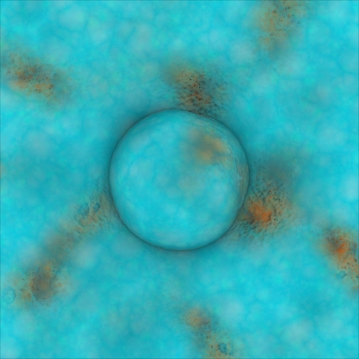
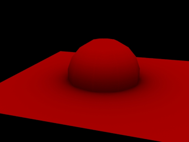
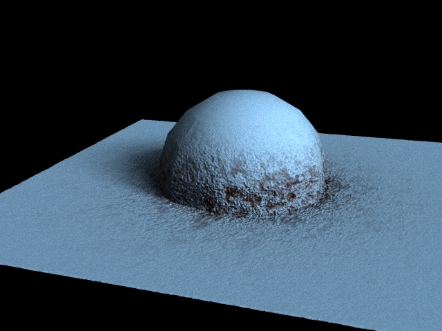
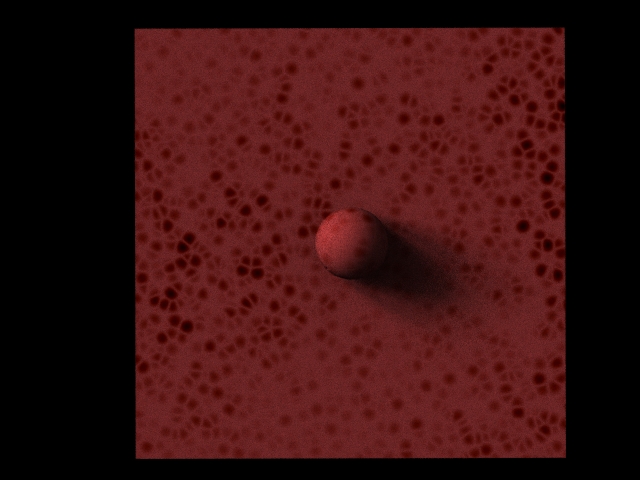
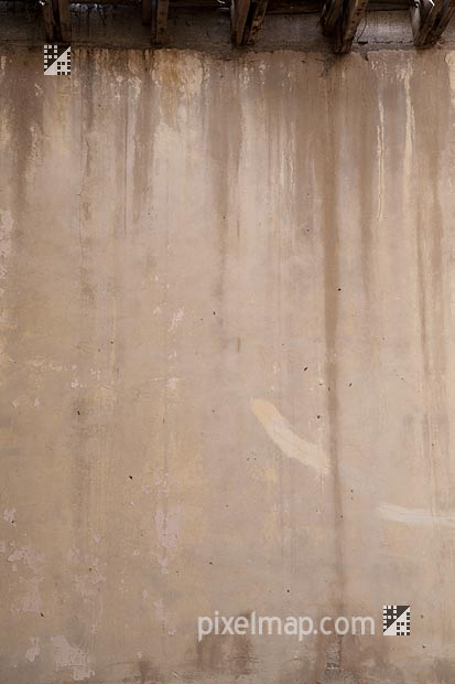
The color of the stains looks to be a derivation of the original wall color, with the edges being slightly different than the center of the stain. Fresh stains are darker towards the center whereas old stains have lifted the color from the center of the stain and the center is less saturated.
The color of the stains looks to be a derivation of the original wall color, with the edges being slightly different than the center of the stain. Fresh stains are darker towards the center whereas old stains have lifted the color from the center of the stain and the center is less saturated.
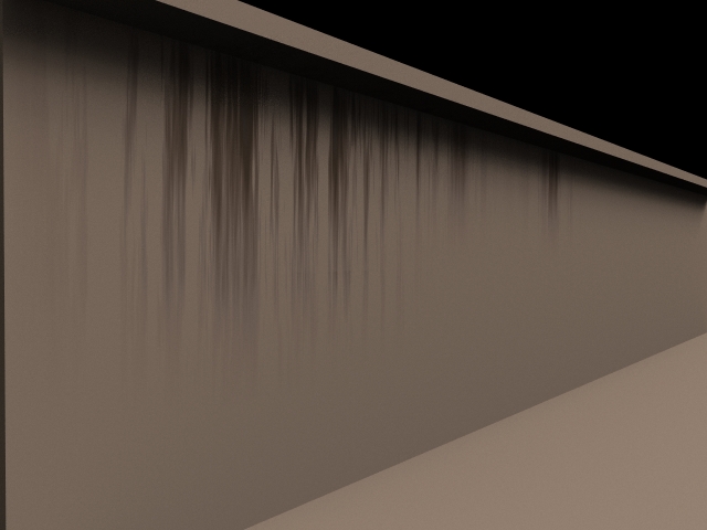
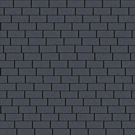
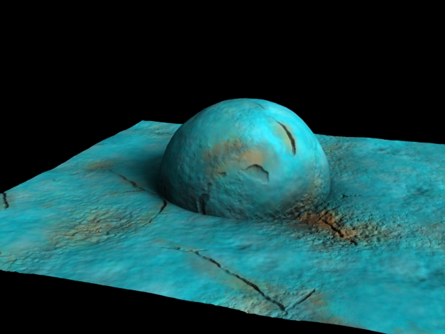
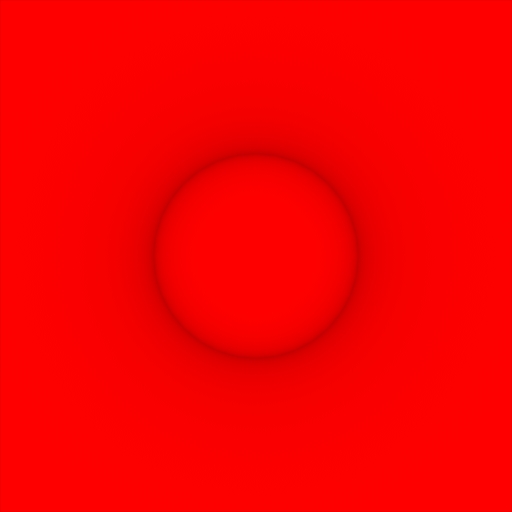
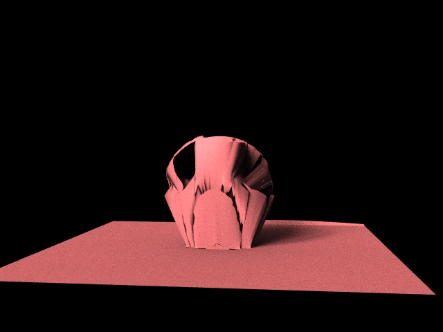
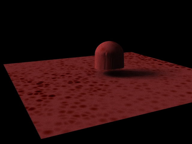
The water stain is based mainly on the Y-axis, the user can change the ramp to control where it goes, as well as paint an attribute on the wall to control where it actually goes.
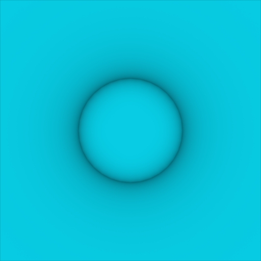
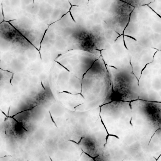
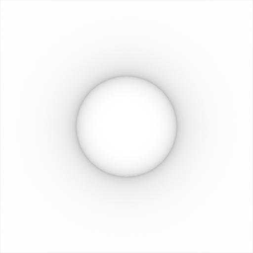
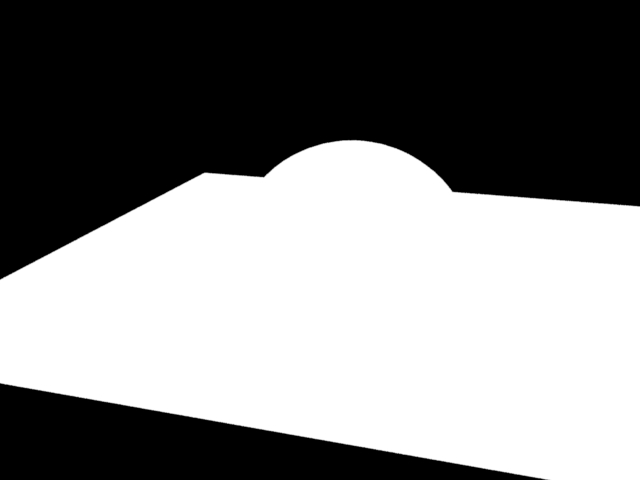
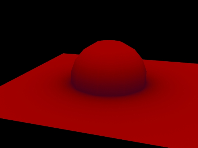
The shape of the drips are controlled by a noise stretched in the Y direction. Roughness controls the amount and frequency of the smaller drips.
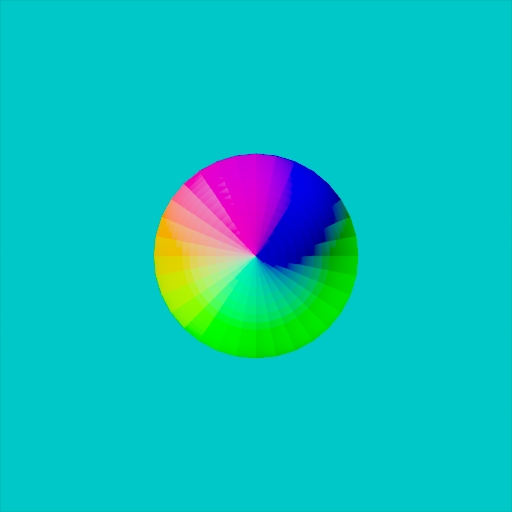
The color is based on the original diffuse of the wall, with changes in the hue, saturation, and value. The user also has the ability to make the center or edges of the stain a different HSV value. This is based on the original intensity of the noise because the center of a noise patch is generally higher in value than the edges.
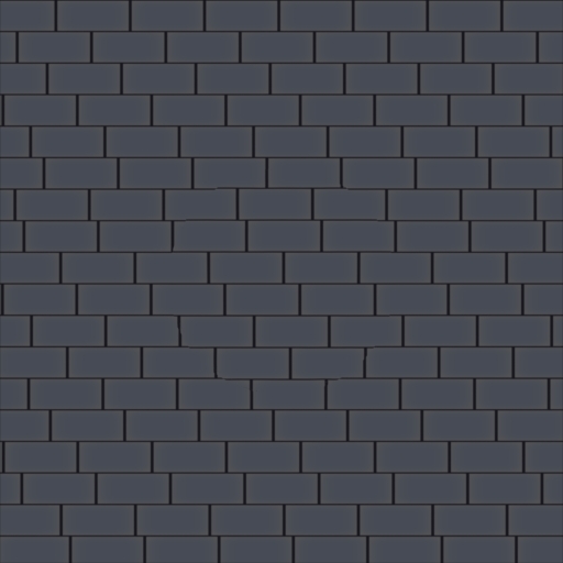
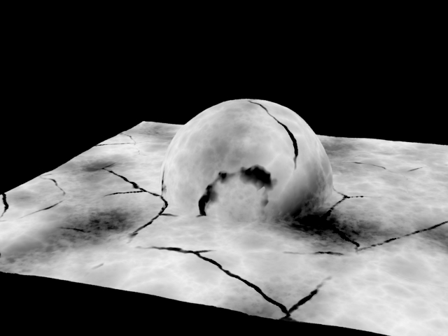
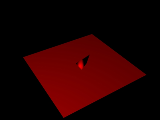
Now I need to python script the ability to paint attributes so the user doesn't have to set/mess that up, also I need to implement the water stains within the cracks. I think the color attribute from the original water stain will be suitable to control that.
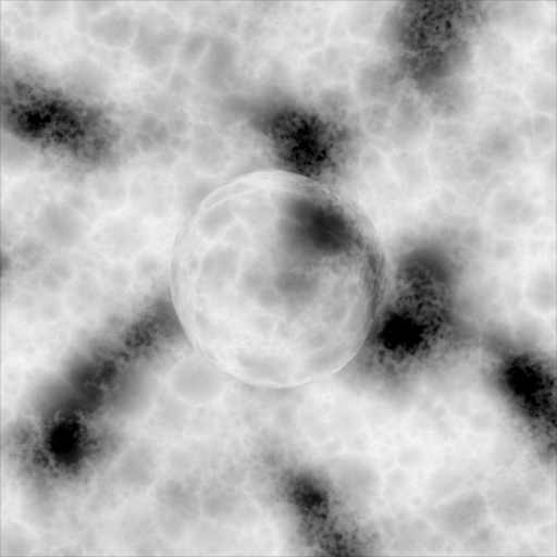
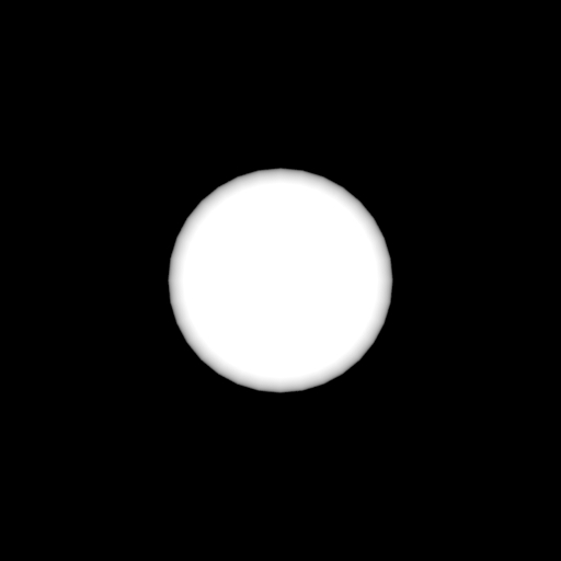
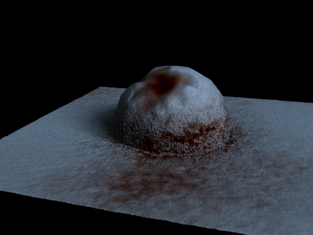
The shape of the drips are controlled by a noise stretched in the Y direction. Roughness controls the amount and frequency of the smaller drips.
The color is based on the original diffuse of the wall, with changes in the hue, saturation, and value. The user also has the ability to make the center or edges of the stain a different HSV value. This is based on the original intensity of the noise because the center of a noise patch is generally higher in value than the edges.
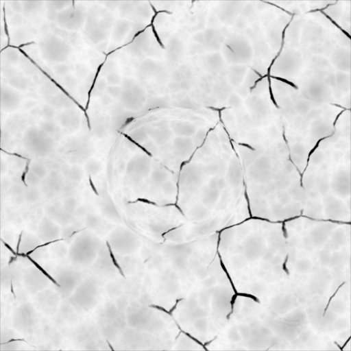
Now I need to python script the ability to paint attributes so the user doesn't have to set/mess that up, also I need to implement the water stains within the cracks. I think the color attribute from the original water stain will be suitable to control that.
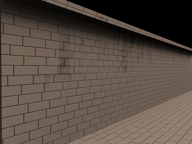
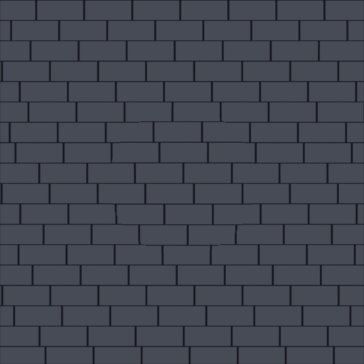
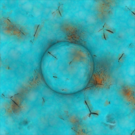
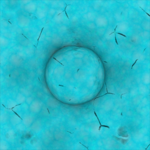
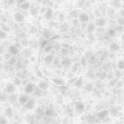
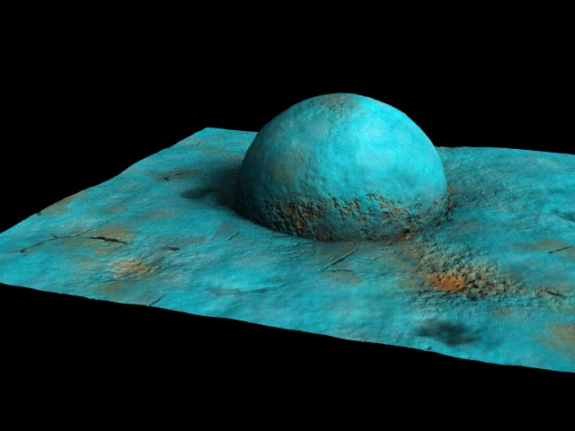
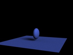
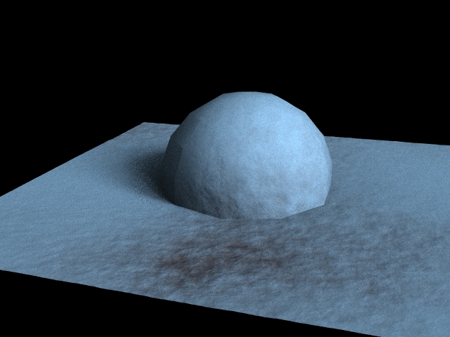
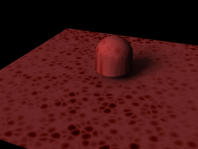
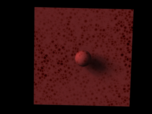
Tile stains have been added! This feature is only available when tiles and water stains are selected. There are two noise functions driving the variation on the tile stains, one large frequency to give broad patterns and a smaller one to break it up and look a bit mouldy.