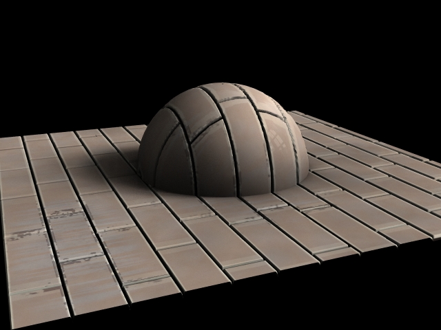

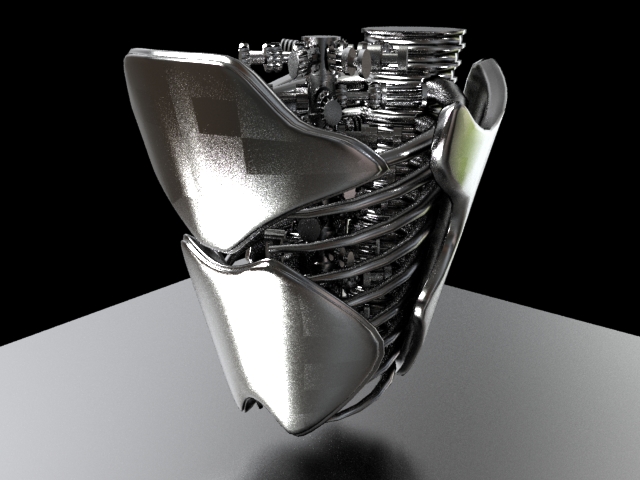
In order to make this a proper shader I have to rework the spec to utilize PBR spec. Something is wrong with my node network right now I think, when I put it on a fancy model, strange square artifacts appear when I turn up the anisotropic bias/angle. It doesn't show up when I use a surface model SOP rather than build my own.
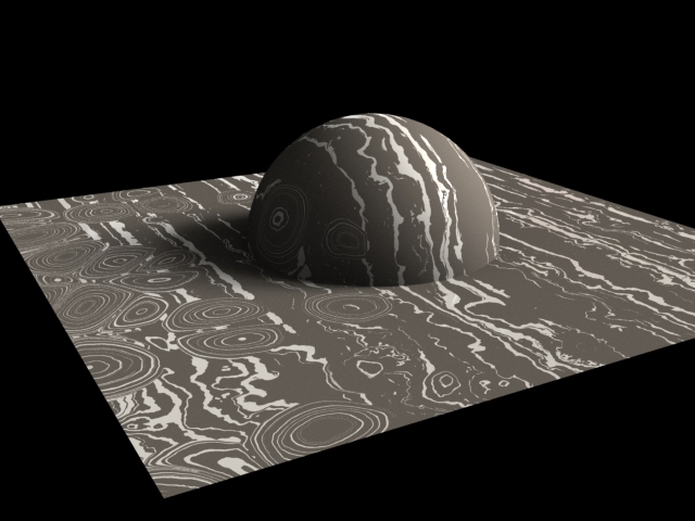
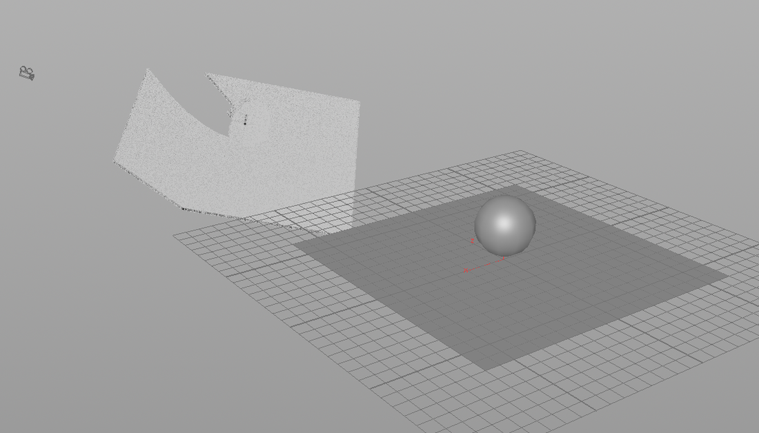
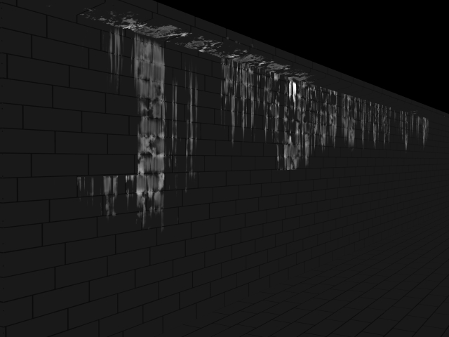
Above Renders:
I've recalculated the normals for the complex model but that doesn't seem to be doing anything.
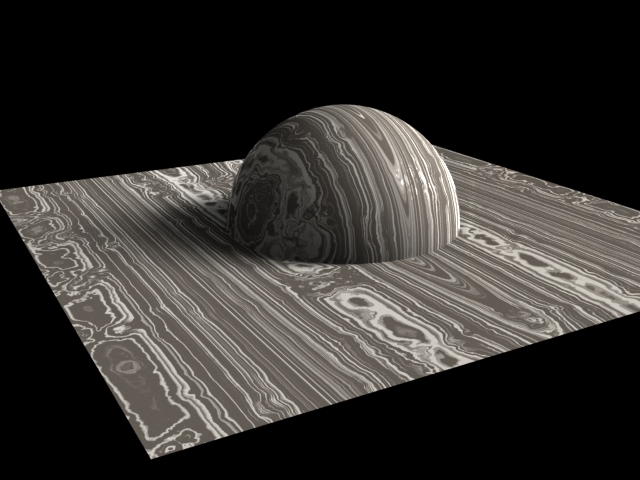
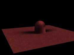
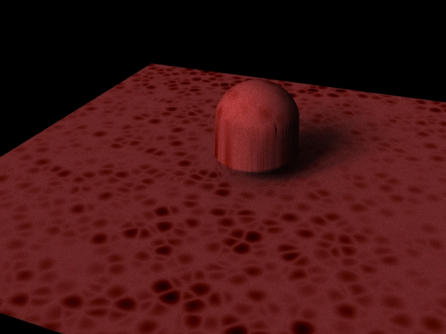
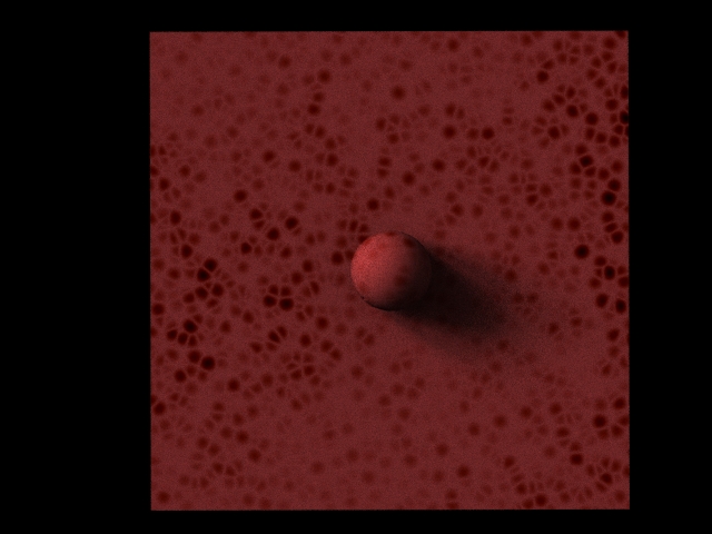
Above Renders:
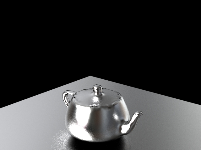
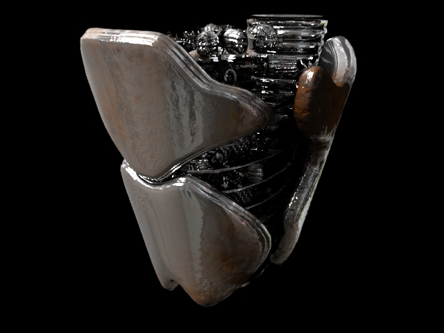
- Complex model with default pbrspecular settings
- Complex model with an Anisotropic Bias of 0.4
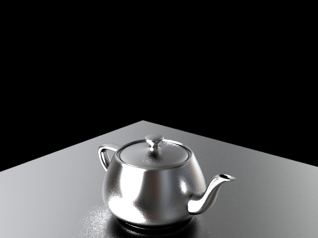
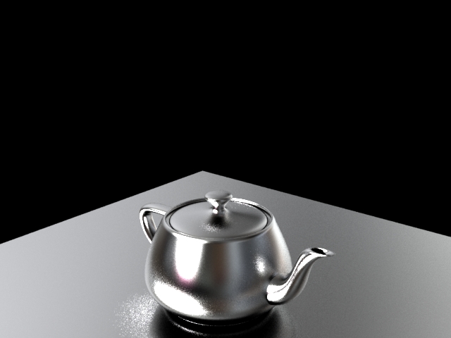
- Polygon soup teapot to get irregular polygons with default pbrspecular settings
- Polygon soup teapot with Anisotropic Bias of 0.4
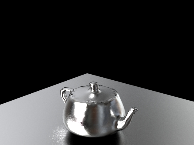
- Default teapot with default pbrspecular settings
- Default teapot with Anisotropic Bias of 0.4
I've recalculated the normals for the complex model but that doesn't seem to be doing anything.
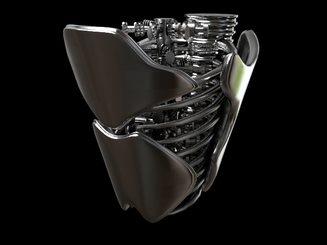

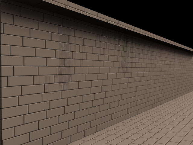
So on the left is a surface model plugged in for the specular and on the right is my shader how I've built it. Apparently I've got the basic setup correct because it finally gave basically the same results as the surface model because both shaders show artifacting! Which means it is the model and not me. I still have to finagle the pbr spec to perfectly match the surface model though which will be a bit more dissecting but at least it's beginning to be accurate.
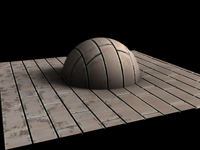
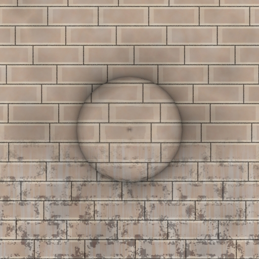
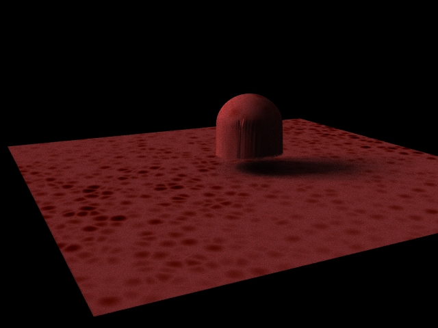
So we're getting somewhere! The spec is working now so I decided to start adding the patterns on and see if the spec holds up. For the most part it does, it works on the object reflections but seemingly not on the light reflections. It still looks a bit glossy on the rust, though it is cutting down a bit.